
Mastermind
This is a page about my final project for ECE 3710: Microcontrollers. You can find the source code on GitHub here.
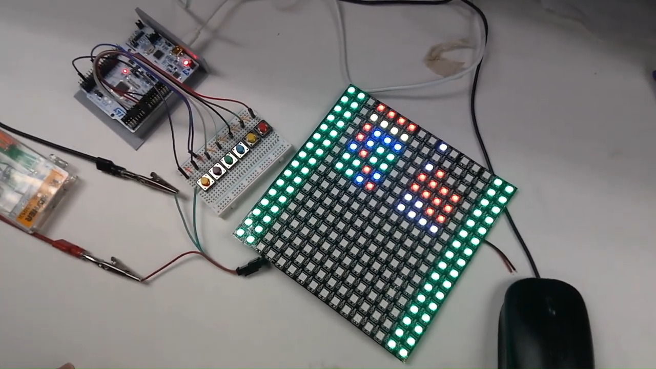
This project, written by myself and a lab partner, implements a digital version of the classic 2-player board game Mastermind for an STM32 microcontroller in C and assembly.
It requires:
- an STM32L476RG microcontroller
- a 16x16 pixel WS2812B LED array
- six push buttons (as currently written, the code assumes they will be red, yellow, green, blue, orange, and purple, in that order)
This project was a lot of fun to work on because of how many topics I was able to touch on while working on it. I created what is essentially a very low-level device driver and basic graphics API for drawing to the LED array.
The WS2812B chip is actually very well supported by various LED libraries, notably FastLED, which every website I went to for help suggested I use. I would have simply used this if the class hadn't been focused on interfacing with a microcontroller's memory map directly rather than relying on libraries such as Arduino (which FastLED depends on).
We considered other options for LED arrays, such as this one from Adafruit. They helpfully proclaim,
Of course, we wouldn't leave you with a datasheet and a "good luck!" We have tutorials and add-on boards that will make connecting and usage very easy!
Again, since none of these tutorials would work with our environment, I decided to look at that datasheet that they mentioned. The datasheet, however, includes no mention of the protocol required to control the thing other than that it uses 13 pins. In reality, the folks at Adafruit left me with no datasheet and a "good luck." I spent only a couple of hours searching for information before I decided that the WS2812B, whose datasheet was obtuse but existent, would probably be a better choice.
Nontrivial effort was required to decipher the WS2812B's datasheet. When I finally did, I realized that communicating with the thing would be a tall task indeed.
The WS2812B chip requires a 5-volt wire, a ground wire, and a data-in signal. It produces a data-out signal, which can be wired to another WS2812B chip. In order to not use a clock, the WS2812B chip interprets the logic HIGH and logic LOW signals on the data-in line in specific ways over specific absolute time intervals as zeroes and ones, forming a sequence of three eight-bit numbers, which are used as the intensity of the green, red, and blue LEDs, in that order. All bits following the initial 24 received are sent on to the next light in the chain.
In particular, each bit takes 1.25μs ± 600ns to transmit. Each bit begins at logic HIGH, and the amount of time the line is held at logic HIGH determines whether the bit is a zero or one.
| Time High | Time Low | Bit Sent |
|---|---|---|
| 400ns ± 150ns | 850ns ± 150ns | 0 |
| 800ns ± 150ns | 450ns ± 150ns | 1 |
Holding the line at logic LOW for 50μs resets the display the next time the line is pulled to logic HIGH.
To figure out just how fast I would need to drive this thing, I wrote a simple python script to calculate the minimum and maximum amount of clock cycles that would comprise each of the different windows:
T0H = 0.40e-6
T1H = 0.80e-6
T0L = 0.85e-6
T1L = 0.45e-6

margin = 150e-9

for spd in [4e6, 8e6, 16e6, 24e6, 32e6, 48e6, 64e6, 80e6]:
    print(f"TIMINGS FOR SPEED={int(spd)}")
    print(f"{'goal':>8}{'min':>10}{'max':>10}{'minclk':>10}{'maxclk':>10}")
    for t in [T0H, T0L, T1H, T1L]:
        mini=t-margin;
        maxi=t+margin;
        print(f"{t:8}{mini:10.2}{maxi:10.2}{mini*spd:10.2f}{maxi*spd:10.2f}")

    print()
Turns out, hitting these windows on the chip we had is no joke. At the default clock speed of 4 MHz, the maximum time for the shortest interval is 2.2 clock cycles, which is not remotely possible to hit.
| Goal (ns) | Min time (ns) | Max time (ns) | Min time (clock cycles) | Max time (clock cycles) |
|---|---|---|---|---|
| 400 | 250 | 550 | 1.00 | 2.20 |
| 850 | 700 | 1000 | 2.80 | 4.00 |
| 800 | 649 | 950 | 2.60 | 3.80 |
| 450 | 300 | 600 | 1.20 | 2.40 |
The windows only begin to be slightly forgiving at 32 MHz, where the maximum time for the shortest interval is 17.6 clock cycles:
| Goal (ns) | Min time (ns) | Max time (ns) | Min time (clock cycles) | Max time (clock cycles) |
|---|---|---|---|---|
| 400 | 250 | 550 | 8.00 | 17.60 |
| 850 | 700 | 1000 | 22.40 | 32.00 |
| 800 | 649 | 950 | 20.80 | 30.40 |
| 450 | 300 | 600 | 9.60 | 19.20 |
I fiddled around for a few hours creating a C procedure, but the exact length of the compiler's code in clock cycles was just too unpredictable.
So I had to go one step further and write an optimized assembly procedure. I'll spare you the exact details, but I was able to hit the timing intervals with the 32 MHz clock with a few clock cycles to spare, even. At a few points, I had to insert no-op instructions to get to the approximate center of the timing window.
Once I had the code communicating with the LEDs, it was time to start defining my API. The first thing to do was set up all the different colors. They went through several variations, but the final colors are defined as follows:
#define BLACK  0
#define RED    1
#define YELLOW 2
#define BLUE   3
#define GREEN  4
#define PURPLE 5
#define ORANGE 6
#define WHITE  7

static uint8_t colors[8][3] = {
    //            GRN   RED   BLU
    [BLACK]  = { 0x00, 0x00, 0x00 },
    [WHITE]  = { 0x10, 0x10, 0x10 },
    [RED]    = { 0x00, 0x20, 0x00 },
    [GREEN]  = { 0x2A, 0x00, 0x03 },
    [BLUE]   = { 0x0A, 0x00, 0x2A },
    [YELLOW] = { 0x25, 0x2A, 0x00 },
    [PURPLE] = { 0x00, 0x15, 0x20 },
    [ORANGE] = { 0x08, 0x35, 0x00 },
};
Note that the highest value
in the entire array
is 0x2A.
These lights burn bright at full intensity.
Even at half intensity,
it can hurt to look at the board too long.
Only by bumping everything down
to a sixth of the maximum value
is it possible to look at these LEDs
at relatively close range.
After that,
it was simply a matter
of decoding the snaking pattern
that the data line followed
to get screen coordinates,
then writing a function to set a pixel.
Further drawing functions
were out of scope of the assignment,
but drawing lines,
circles,
and other objects
with only the aid of a pixel setting function
is a well-explored field;
thus its implementation
is left as an exercise
to the reader.
The set_pixel function
is included below:
void set_pixel(
    uint8_t *image,
    const uint8_t x,
    const uint8_t y,
    const uint8_t color,
) {
    uint8_t yoffset = x % 2 ? (15 - y) : y;
    uint8_t xoffset = (15 - x) * 16;
    uint8_t idx = xoffset + yoffset;

    image[idx] = color;
}
image is a buffer of 256 eight-bit integers,
each representing a color in the colors array
included in the snippet above the last.
These are turned into
their corresponding three-byte representations,
which are sent to the array at the end.
The rest of the project including the button interface, the microcontroller initialization, and the game logic were interesting to implement but they were not novel for me so I won't go over any of it here.
Tags: #microcontrollers #gamedev #c #assembly